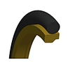


Gzt - High Quality PTFE Hydraulic Rod Seal with NBR/FKM O-Ring
GZT
Quantity:
1. Application and properties
Suitable for single-acting or double-acting rod seal, and has good sealing performance at medium and low pressure, with very little leakage. It has low friction coefficient and can work with or without lubrication, and can be used for oil-free lubrication cylinder seals. It is recommended to prioritize for servo cylinders requiring rapid response. It can be used for special conditions such as extremely high speed, extremely low speed, micro-stroke etc.
The working medium adaptability and working temperature range can be changed by replacing the material of the O-ring.
The installation groove is small, which is conducive to design cylinder size. The seal is easy to install and generally does not require special tools.
Compliant with GB/T 15242.1-94 and GB/T 15242.3-94 standards.
Products of different sections can be selected according to the size of the actual working pressure value, in principle, the greater the working pressure, the larger the cross-section should be selected.
2. Standard Material
Sealing ring: filled PTFE
O-Ring: NBR / FKM
3. Working conditions
Working Conditions | ||||
Diameter Range | Pressure Range | Temperature Range°C | Speed | Medium |
4~2000mm | 0~25MPa | -30~100(NBR) -20~160(FKM) | 1.5m/s | Hydraulic oil, flame retardant liquid, water, gas |
4. Related Dimensions
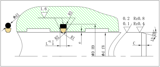
R1=0.3~0.5; R2=0.1~0.2; R3=0.5~1; e=0.2~0.5; C=(0.5~0.7)L. The specific values are selected according to the section size of the seal. The remaining values are listed in the table below:
| Rod Diameter d | Groove | Groove | Radial Clearance e | O-Ring | ||||
| Diameter | Width | Cross-Section | ||||||
| Standard | Light | Heavy Duty | D | L | 10 | 20 | 40 | d1 |
| Application | Application | Application | MPa | MPa | MPa | |||
| 3~7.9 | 8~18.9 | — | d+4.9 | 2.2 | 0.3 | 0.2 | 0.15 | 1.78 |
| 8~18.9 | 19~37.9 | — | d+7.3 | 3.2 | 0.4 | 0.25 | 0.15 | 2.62 |
| 19~37.9 | 38~199.9 | 8~18.9 | d+10.7 | 4.2 | 0.4 | 0.25 | 0.2 | 3.53 |
| 38~199.9 | 200~255.9 | 19~37.9 | d+15.1 | 6.3 | 0.5 | 0.3 | 0.2 | 5.33 |
| 200~255.9 | 256~649.9 | 38~199.9 | d+20.5 | 8.1 | 0.6 | 0.35 | 0.25 | 6.99 |
| 256~649.9 | 650~999.9 | 200~255.9 | d+24.0 | 8.1 | 0.6 | 0.35 | 0.25 | 6.99 |
| 650~999.9 | ≥1000.0 | 256~649.9 | d+27.3 | 9.5 | 0.7 | 0.5 | 0.3 | 8.4 |
| ≥1000.0 | — | 650~999.9 | d+38.0 | 13.8 | 1 | 0.7 | 0.6 | 12 |
5. Marking method
Mark it with the dimension of installation groove
For example: The standard type φ100 rod seal is marked as GZT100×115.1×6.3
6. Installation Dimensions
Refer to GSI Installation Dimensions table