
Spring Energized Seal (Variseal) Installation Manual
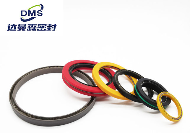
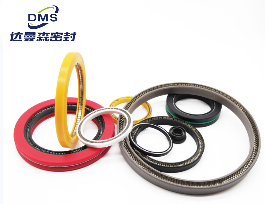
Spring‑energized seals rely on springs to deliver continuous preload, compensate for wear, resist corrosive media, and serve reciprocating, rotary and static sealing applications over a wide temperature range.
Energized seals (PTFE sliding ring + stainless steel spring construction) are also “delicate components” among seals. The thin‑walled PTFE sliding ring is vulnerable to scratches, the energizing spring risks dislodgement, and the sealing lip cannot be fitted backwards. While ordinary rubber seals can tolerate rough handling to some extent, energized seals are easily ruined by heavy‑handed assembly. Many early leaks on production lines stem not from the seal itself, but from improper assembly practices. This document clarifies the three critical assembly failure points, the five‑step standard procedure and four non‑negotiable rules at once.
Ⅰ Three Critical Assembly Failure Points — Any One Will Cause Leakage
- Scratch risk for sliding ring: Thin‑walled PTFE sliding rings have no elastic recovery. Contact with sharp edges or burrs will cause permanent damage upon assembly.
- Spring dislodgement risk: If the energizing spring shifts or falls out, preload is lost and the seal becomes ineffective.
- Reversed lip risk: Shaft seals and bore seals follow different assembly logic. A reversed lip leads to direct reverse leakage.
Ⅱ Five‑Step Standard Installation Procedure (General for Shaft & Bore Types)
1. Inspect components
Verify the integrity of the seal body and spring; distinguish between shaft‑type and bore‑type seals and confirm the correct energizing direction of the spring.
2. Prepare the groove
Remove burrs and clean the groove. Apply the recommended lubricant evenly to reduce insertion resistance.
3. Assemble with tooling
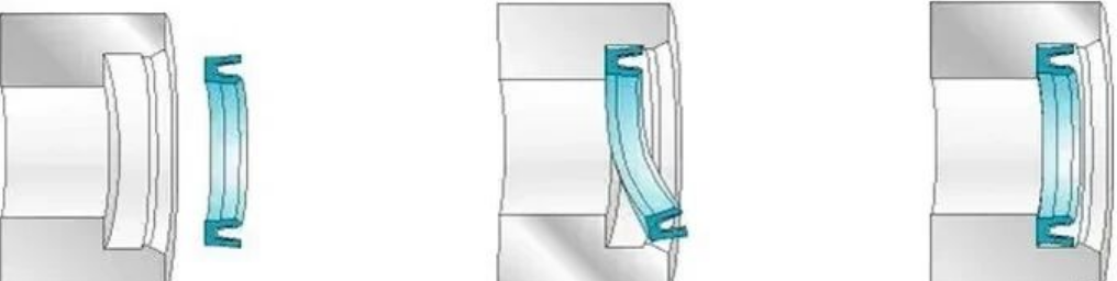
Use dedicated tooling such as installation sleeves and lead‑in cones. Never pry the seal by force manually; protect the sliding ring and spring.
4. Reconfirm component alignment
Double‑check lip orientation and spring position. Ensure no twisting or offset.
- Post‑assembly inspection
Ⅲ,Carry out visual inspection and low‑pressure leak test. Confirm acceptance before installation on equipment — do not let the finished equipment bear the risk of poor assembly.
Proper training cuts assembly failures by 90%
A high‑pressure valve manufacturer frequently suffered from scratched PTFE sliding rings and dislodged springs during assembly, resulting in a high leak rate under pressure holding. After training the assembly team using this installation manual:
Assembly‑related seal failures reduced by 90%
First‑pass yield and pressure‑holding qualification rate of test assemblies improved significantly
Customer feedback: “The manual is straightforward. It highlights protection points for springs and sliding rings, and rework on the production line has dropped noticeably.”
Why does the Glyd Ring/GSF achieve nearly zero friction?